 |
vintage radio wireless valve museum tube vintage marconiphone DER car radio
|
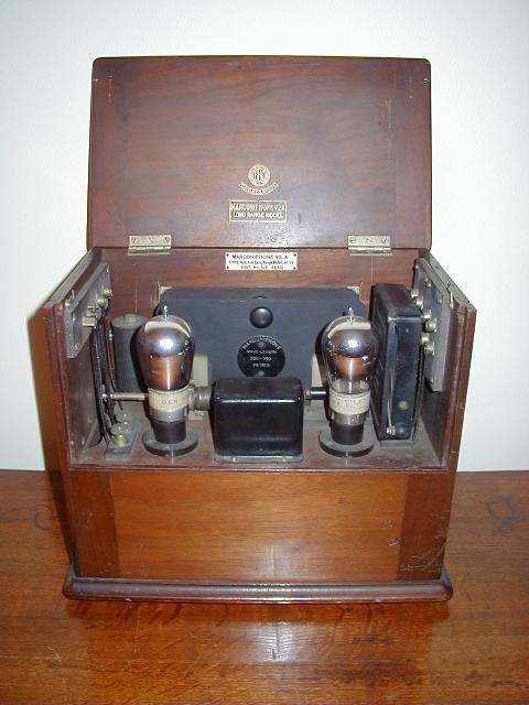
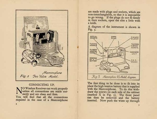
This is the Marconiphone Model V2A ('Long Range Model') manufactured in 1923 by Marconi's Wireless Telegraphy Co, Ltd. (chassis manufactured by Plessey, Holloway, London). The instrument is housed in a polished mahogany cabinet bearing the 'BBC/PMG' stamp and GPO Registration No. 0175. A contemporary advertisement for a similar model, the V2, is reproduced below. The price of £24, complete, was a considerable sum of money in 1923 and included £1 15s royalty paid to the BBC and 12s 6d per valve royalty paid to the Marconi company.
 |
The circuit of the V2 (identical it seems to the V2A) is shown below.
 |
|
Circuit of the Marconiphone V2 Receiver from 'Wireless Telephony and Broadcasting' Vol. II by H. M. Dowsett M.I.E.E., F.Inst.P., M.Inst.R.E., pub.: The Gresham Publishing Company Ltd., London 1923. |
This is an unusual two valve regenerative TRF* reflex design. Its operation is as follows:
*Tuned Radio Frequency
OVERALL OPERATION
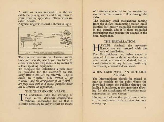
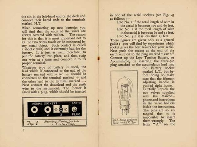
The aerial (antenna) is connected, depending upon its length, to the appropriate 'AERIAL' terminal, 1, 2 or 3. Aerials have a certain natural capacitance to ground and the longer the aerial the greater the capacitance. This capacitance appears across the aerial tuning circuit, thereby affecting its resonant frequency. Now the aerial tuning circuit needs to cover much the same wavelength range for aerials of substantially different lengths (and therefore different capacitances). Medium length aerials of approximately 50' (15.25m) are connected to terminal 2 and thence via a coupling capacitor to the aerial tuner. Aerials much longer than this (up to approximately 100') are connected to terminal 1 where a smaller value of coupling capacitor is used which reduces the capacitive loading on the tuned circuit to roughly that of a 50' aerial. Short aerials are connected to terminal 3 where the act of inserting the aerial plug causes a capacitor to be connected between the aerial and earth, raising the overall aerial capacitance up to roughly that of a 50' aerial. In this way the aerial tuning circuit is always loaded by roughly the same aerial capacitance. Hence the range of wavelengths covered remains substantially constant for different lengths of aerial.
The first valve amplifies the RF signal from the aerial tuner and the output from its anode is tuned and fed to the second valve which is wired as a grid-leak detector. The grid-leak resistor is marked 2W which is the archaic way of writing 2MW. The output from the detector anode contains the recovered audio signal and a certain amount of the carrier wave RF as well. This RF output is series tuned by the REGENERATIVE UNIT and fed back to the detector input with the correct phase needed to achieve positive feedback. The setting of the lever on the REGENERATIVE UNIT influences the strength of feedback and hence the selectivity of the circuit.
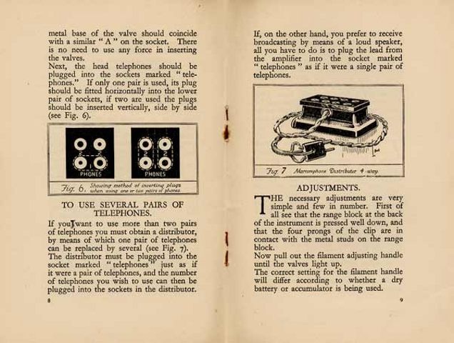
The audio output from the detector is connected to the (low impedance) primary of an LF feedback transformer. The audio output from the (high impedance) secondary of this LF feedback transformer is connected to the grid of the first valve via an RF choke. The first valve then amplifies this audio signal before coupling it to the headphones via another RF choke.
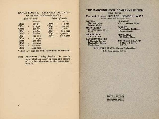
PLUG-IN TUNING RANGE BLOCKS
A number of plug-in tuning range blocks cover wavelengths from 300 to 2900 metres. Each block contains two 'pancake' coils which provide aerial (antenna) and RF amplifier anode-tuning respectively. A pair of ball-end tuning rods project through the side walls of the cabinet, one to the left and one to the right. To the inner end of each rod is attached a copper plate or spade. As the rods are slid in and out of the cabinet the copper plates are caused to slide across their respective pancake coils and thereby influence the tuning. The following list from a contemporary publication gives an insight into what one could receive using this set:
300-390 m. for British broadcasting
390-530 m . for British broadcasting
550-700 m. for shipping
700-900 m. for aircraft
2500-2900 m. for Paris
PLUG-IN REGENERATOR RANGE BLOCKS
A plug-in regenerator range block ('REGENERATIVE UNIT') provides the adjustable regeneration. A number of these plug-in regenerator range blocks were available to cover the tuning range. Each ebonite range block houses a tuning inductor and coupling capacitor. The inductor is tuned by means of an integral copper disc attached to a control lever.
FILAMENT RHEOSTAT
Originally this circuit used 'R' type bright emitter valves which were susceptible to failure due to the very high temperature of the filament. A rheostat was provided to control the filament current and thereby prolong (or otherwise!) the life of these expensive valves. Later sets retained this rheostat when 'DER' (Dull Emitter 'R') valves were introduced. The rheostat is operated by another control rod protruding from the side of the cabinet. When the rod is pushed right in, the filament circuit is disconnected from the accumulator.
BATTERIES
The set was designed for battery operation and provision is made for connection of an external LT accumulator and HT battery (no grid bias required). The HT battery could, if desired, be housed within the lower half of the cabinet.
DETACHABLE PANELS
The set has a pair of detachable panels at the front. The top panel features two viewing portholes which were used to keep an eye on the valve filaments. The bottom panel is held with two screws and covers a void where the HT battery could be housed.
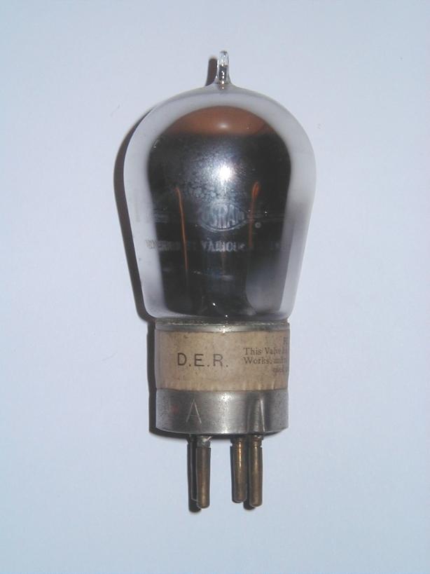
VALVES
Most sets sold would probably have used the Marconi-Osram 'DER' valve which required 1.8V at 0.4A for the filament.
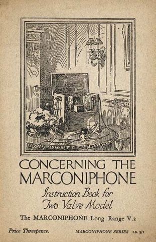
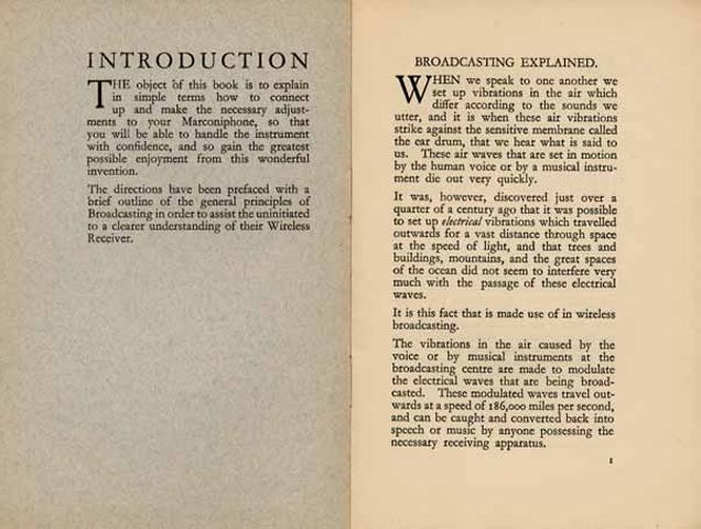
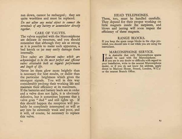
INSTRUCTION BOOKLET
The following comprehensive instruction booklet for the V2 was produced by Marconi's Wireless Telegraphy Co, Ltd.:
'Image reproduced from www.marconicalling.com courtesy of Marconi plc.' |
'Image reproduced from www.marconicalling.com courtesy of Marconi plc.' |
'Image reproduced from www.marconicalling.com courtesy of Marconi plc.' |
'Image reproduced from www.marconicalling.com courtesy of Marconi plc.' |
'Image reproduced from www.marconicalling.com courtesy of Marconi plc.' |
'Image reproduced from www.marconicalling.com courtesy of Marconi plc.' |
'Image reproduced from www.marconicalling.com courtesy of Marconi plc.' |

'Image reproduced from www.marconicalling.com courtesy of Marconi plc.' |
'Image reproduced from www.marconicalling.com courtesy of Marconi plc.' |
'Image reproduced from www.marconicalling.com courtesy of Marconi plc.' |
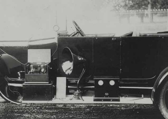
EARLY CAR RADIO?
V2s mounted on British motor cars (I wonder if people trying to tune their V2s whilst on the move were regarded then in the same way as those using their mobile phones while driving are nowadays!)
|
left click for larger image 'Image reproduced from www.marconicalling.com courtesy of Marconi plc.' |
|
left click for larger image 'Image reproduced from www.marconicalling.com courtesy of Marconi plc.' |
![]()
![]()
Copyright Ó 2000 - 2002 Lorne Clark
