 |
bth type c form a crystal set vintage radio wireless detector variometer museum vintage headphones
|
|
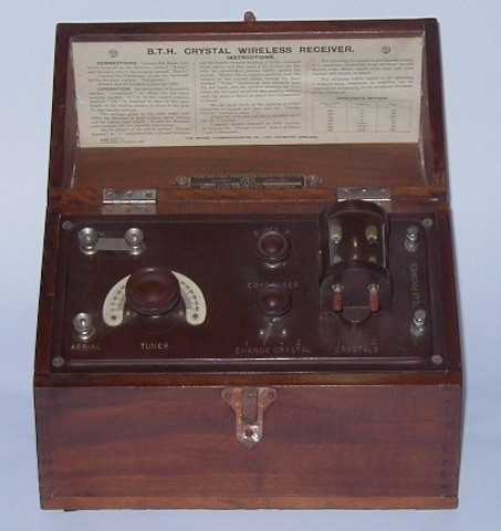
This is the BTH Type 'C' Form 'A' twin detector crystal set manufactured by British Thomson Houston Ltd. in 1924. It bears the BBC/PMG stamp marked with the GPO Reg. No. 106. The lift up lid carries the comprehensive instructions for use. The date of manufacture is printed in the lower left corner of the instruction card. This type of crystal set was manufactured by BTH from 1922 through to 1925.
The set is housed in a solid walnut cabinet and features silent variometer* tuning, twin galena/catswhisker detectors and selectable aerial (antenna) coupling.
*a variometer is a rotary variable inductance typically used for aerial tuning
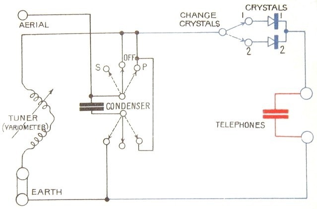
The circuit diagram for the receiver is reproduced below:
 |
|
Circuit of the BTH Type 'C' Form 'A' circuit diagram from 'Wireless Telephony and Broadcasting' Vol. II by H. M. Dowsett M.I.E.E., F.Inst.P., M.Inst.R.E., pub.: The Gresham Publishing Company Ltd., London 1923. |
The aerial is coupled to the variometer via the 'CONDENSER' and it's selector switch. In the 'OFF' position the aerial is connected directly to the variometer tuner. This suits aerials approximately 50 feet long. Aerials up to approx. 100 feet (the maximum allowable at the time) can be accommodated by selecting the 'S' position. In this position the 'CONDENSER' is connected in series with the aerial, reducing the capacitive loading on the vartiometer to that of a 50 foot aerial. Where only a short aerial was available, the switch would be set to the 'P' position whereby the 'CONDENSER' would be connected between the aerial and earth, increasing the capacitive loading on the variometer to that of a 50 foot aerial. Keeping the capacitive loading on the variometer constant ensured a constant tuning range. Only one detector is in use at any one time, the selection being made with the 'CHANGE CRYSTALS' switch.
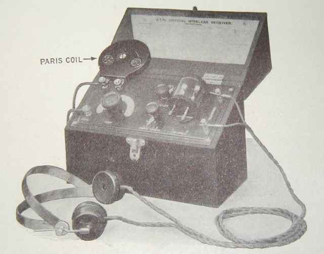
The two terminals in the earth return lead from the variometer (at top left of the front panel) were used for attaching a long-wave 'loading coil'. Coils for the Paris time signals (2600 metres) and the BBC '5XX' station (1600 metres) were available and could be connected to the terminals after first removing the shorting link. A contemporary picture (below) shows one of these loading coils in use:
 |
|
Picture of the BTH Type 'C' Form 'A' with Paris loading coil fitted. From 'Wireless Telephony and Broadcasting' Vol. II by H. M. Dowsett M.I.E.E., F.Inst.P., M.Inst.R.E., pub.: The Gresham Publishing Company Ltd., London 1923. |
![]()
![]()
Copyright Ó 2001 - 2002 Lorne Clark