|
|
vintage radio wireless crystal valve museum boatanchor tube vintage gecophone gec bc2935 KL1 P.8 P625A U5
|
|
This rather ornate set is the GECoPHONE BC2935 'All-Electric' 3-valve receiver from 1928 and is thought to be the very first mains driven GECoPHONE set. It is a 3 valve (plus rectifier) TRF set and is housed in a polished mahogany cabinet with marbled ebonite inset front panel. The lid bears the 'BBC/EBM' stamp.
Four front panel controls are provided. From left to right these are as follows:
|
'RANGE' |
selects either MW or LW |
| 'INTENSIFIER' | more usually known as the 'reaction' control, this varies the selectivity of the set |
| 'SELECTOR' | this is the tuning control |
| 'VOLUME CONTROL' | varies the output level to the (external) speaker. |
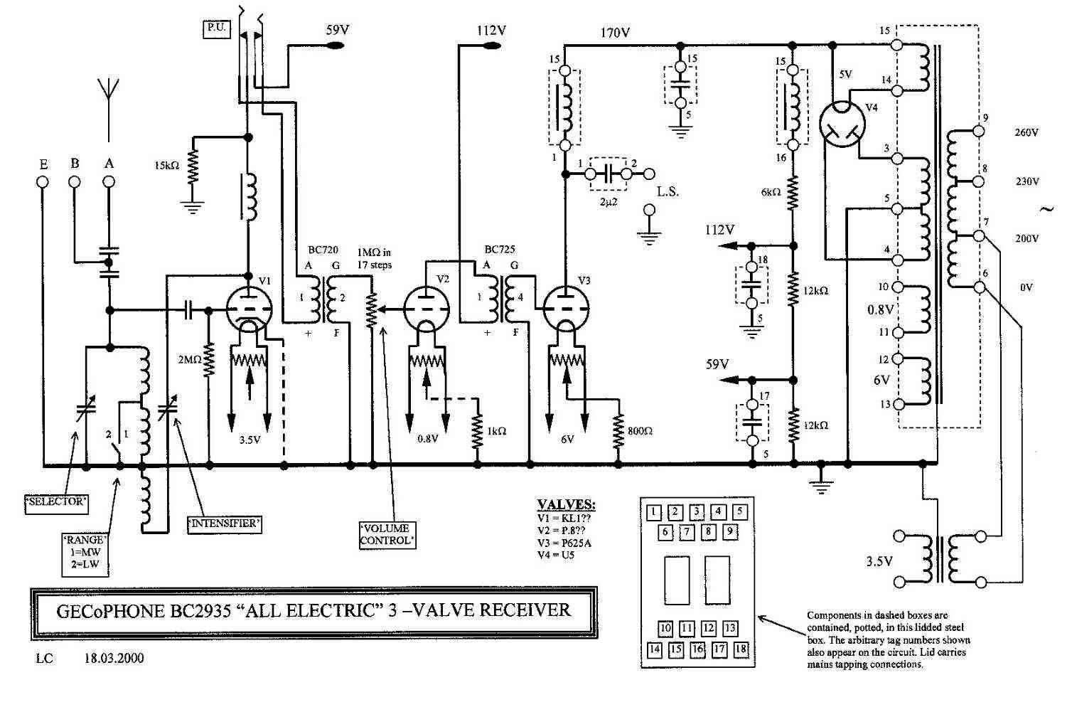
The circuit diagram for this set is shown below (to see a larger printable image click on the circuit):
 |
|
GECoPHONE BC2935 circuit diagram |
This circuit has been traced from the actual set in my collection. Because my set has been modified 'in antiquity', it represents my best guess as to what the original would have been like. V1 is thought to have been an Osram KL1 which was a very early valve of the indirectly-heated-cathode type and designed specifically for AC heater operation. V2 is thought to have been an Osram P.8 (Pee-point-eight). The 'point-eight' series of directly-heated-cathode valves were only produced for a very short time and had a heater voltage of 0.8V (800mV). This allowed Osram to use a very low impedance heater which in turn reduced the hum that would otherwise arise with the use of a directly heated cathode. Audio output valve V3 is a P625A and the full-wave rectifier is a U5.
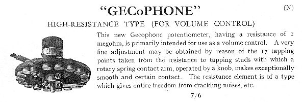
The aerial (antenna) is connected to either terminal 'A' or terminal 'B' dependant upon its length. Long aerials were connected to 'A' and medium length aerials to 'B'. The additional coupling capacitor in series with long aerials connected to terminal 'A' keeps the capacitive loading on the aerial tuner roughly the same as for medium length aerials connected to 'B'. V1 acts primarily as a detector of the grid-leak type. However, it is also acting as an RF amplifier for use within the reaction circuit. The RF output from V1 anode is coupled to the reaction circuit comprising the 'INTENSIFIER' variable capacitor and the lower winding on the aerial tuner. The positive feedback obtained is used to improve selectivity and sensitivity. The audio output from V1 is coupled via an RF choke and the pick-up jack-socket to the primary of the 1st interstage transformer. The secondary of this transformer is coupled to the grid of V2 via the 'VOLUME CONTROL'. This volume control is in the form of a 1M Ohm 17 position rotary stepped resistance with large brass contacts and a brass-leaf wiper (picture below). The audio output from V2 anode is coupled to the grid of V3 by means of the 2nd interstage transformer. V2 is a power triode who's output is coupled to the external loudspeaker via a 2.2uF capacitor.
 |
|
Contemporary advertisement for the GECoPHONE high-resistance volume control |
Coupling capacitors are of the old GECoPHONE 'wire-wound' type. These were quite unusual and were made as follows: A metal rod was covered with a thin layer of insulation (celluloid?) and over this was wound a coil of tinned copper wire, the turns of which were shorted with solder to make them non-inductive. One connection was made to the metal rod and the other to the winding layer. These capacitors were used extensively in early GECoPHONE sets.
The tuning 'SELECTOR' condenser is a real work of art with three stages of drive reduction using anti-backlash sprung discs. Follow the link to have a look. The dial on my set still bears the pencil written names of many 1920s UK and European stations including 2LO.
Each valve has its own separate heater winding. One oddity is that V1 heater even has its own separate mains transformer! Why this was done is not entirely clear but could indicate a last minute change of direction by the design team. The first valve in such a receiver is highly susceptible to hum from the heater circuit. I suppose it is possible that the designers had originally intended to use one of the 'point-eight' series here but found that the hum was unacceptable and had to fit an indirectly-heated-cathode type instead. This is pure conjecture of course. Another possibility is that the second mains transformer was added later to accommodate a KL1 or similar 3.5V valve. The fact that the second mains transformer has only one mains tap would tend to support this theory. However, the transformer is very old with heavy fabric bindings and must surely be roughly the same age as the rest of the set. If anyone knows the true reason behind this odd arrangement, please could they let me know.
Each heater (except the rectifier) has a hum-bucking pre-set potentiometer wired across it. These hum-buckers were designed to minimize the hum arising from the use of directly heated valves. Notice that V1 retains its hum-bucker in spite of having an indirectly heated cathode. This could either be because the type KL1 valve had poor heater cathode leakage (unknown but likely) or it could be further evidence that V1 was originally intended to be a 'point-eight' series directly heated valve.
As noted on the circuit diagram, the mains transformer and several other components, including HT smoothing components, were potted in a large lidded steel box. The potting medium is a black wax and connections are via 18 solder tags also embedded in the wax. How the manufacturers made such a neat job of this potting I really don't know; it is superb.
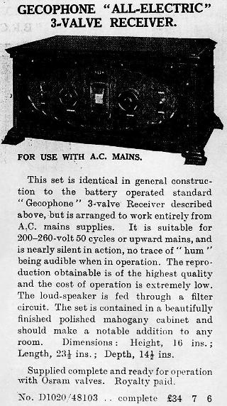
This set is still in working order, although it was modified sometime in the early 1930s to take advantage of what were then more modern valves in V1 and V2 locations. Finally, below is a contemporary advertisement from a catalogue by Cadison of 5 & 6 Red Lion Square, London W.C.1., England.
 |
|
Contemporary advertisement for the GECoPHONE BC2935 |
This price represented a significant outlay in 1928 and could only have been afforded by the well off.
![]()
![]()
Copyright Ó 2000 - 2001 Lorne Clark
