|
|
gecophone bc2001 vintage radio wireless grid leak detector variometer museum vintage gec reactance reaction horn loudspeaker headphones
|
|
This is the GECoPHONE two valve receiver model BC2001 sitting atop its matching two stage LF amplifier model BC2580, both units built by GEC (UK) in 1922. The receiver bears the BBC/PMG stamp and GPO Registration No. 2000 whilst the LF Amplifier bears the BBC/PMG stamp and GPO Registration No. 3360.
BC2001 Receiver
Housed in a polished mahogany 'smoker's cabinet', the receiver features a polished black ebonite panel bearing the following controls (clockwise from top left): aerial tuning variometer, anode tuning condenser, filament current rheostat, HT on/off switch. Two doors, carrying the operating instructions, close to protect the control panel when not in use. A third, full width, door conceals the HT battery compartment. The black bakelite tuning dials marked 'VARIOMETER' and 'CONDENSER' respectively are calibrated 0 to 180 degrees. Sockets are provided for additional aerial tuning coils called Loading Coils. These loading coils, fitted in place of the shorting link situated centrally just above the tuning dials, enabled the aerial to be tuned to different wave bands. Just above the ebonite panel is a recessed wooden panel carrying 3 4-pin sockets. The two outer sockets are for the valves, whilst the middle socket carries the REACTANCE UNIT. The reactance unit is in two parts: a loosely coupled RF transformer and a screw-on damping plate. One winding of the transformer acts as the first-stage anode tuning inductor, whilst the other winding is the reaction feedback winding. The damper plate controls the degree of coupling between the two windings.
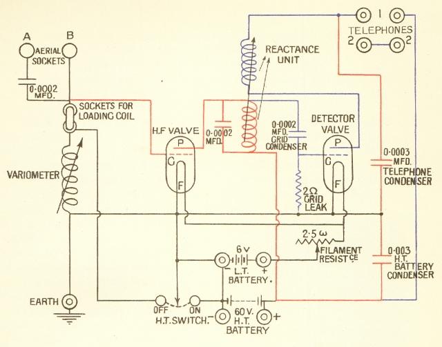
The circuit diagram for the receiver is reproduced below:
|
|
|
Circuit of the GECoPHONE 2 Valve Receiver BC2001 from 'Wireless Telephony and Broadcasting' Vol. II by H. M. Dowsett M.I.E.E., F.Inst.P., M.Inst.R.E., pub.: The Gresham Publishing Company Ltd., London 1923. |
OVERALL OPERATION
This is a 2 valve TRF set with 1 stage of RF amplification and a grid-leak detector. Two stages of tuning are provided: aerial (antenna) tuning and 1st stage anode tuning. The aerial is connected, depending upon its length, to the appropriate 'AERIAL' terminal A or B. Aerials have a certain natural capacitance to ground and the longer the aerial the greater the capacitance. The variometer is simply a variable inductance which is adjusted to resonate with the aerial capacitance at the particular wavelength of interest. The range of variometer adjustment is chosen so that aerials of up to 60' connected to socket B can be tuned to the MW band. Aerials longer than this (up to approximately 100') are connected to terminal A where a small value of coupling capacitor is used to reduces the effective aerial capacitance so that the variometer can still tune the MW band. To cater for tuning longer wavelengths, the aerial tuning inductance can be increased by replacing the normal shorting link with a suitable LOADING COIL. Several different loading coil inductances were available and an example is shown below.
|
|
|
Example of a LOADING COIL labelled '300 BC1360'. The figure '300' indicates that it has an inductance of 300mH; BC1360 is the model number. |
The first valve amplifies the RF signal from the aerial tuner and its anode is tuned by the front panel CONDENSER and the main winding of the REACTANCE UNIT. The RF signal is then fed to the second valve which is wired as a grid-leak detector. The grid-leak resistor is marked 2W which is the archaic way of writing 2MW. The output from the detector anode contains both the recovered audio signal and a certain amount of RF as well. This RF output is coupled back to the detector input via the regenerative winding of the REACTANCE UNIT and with the correct phase needed to achieve positive feedback. The strength of feedback, and thereby the RF gain of the detector stage, can be varied by means of the damper plate. When the damper plate is screwed close to the coil the feedback is small and the sensitivity is low. As the damper plate is wound further away from the coil the positive feedback increases and the sensitivity rises. Care must be taken not to move the damper plate too far from the coil as too much positive feedback would cause the stage to oscillate.
The audio output from the detector is connected to the sockets marked 'TELEPHONES'. The TELEPHONE CONDENSER between the audio output and earth de-couples the RF signal.
PLUG-IN REACTANCE UNIT
The plug-in 'REACTANCE UNIT' provides both the RF amplifier anode tuning inductance and adjustable regeneration. An example of this device is shown below:
 |
 |
|
Example of a plug-in REACTANCE UNIT labelled '40R775 A'. The number '775' indicates the resonant wavelength with the CONDENSER in the middle of its range, whilst the number '40' is thought to indicate the coupling factor. |
|
A number of these plug-in REACTANCE UNITS were available to extend the tuning range. Each ebonite reactance unit houses a tuning inductor and feedback inductor. The mutual inductance is controlled by means of a brass damper plate. The use of brass, having a permeability of less than unity, enables the mutual inductance to be reduced as the plate is wound closer to the coils.
FILAMENT RHEOSTAT
The valves originally fitted to this receiver were 'R' type bright emitter valves. The filaments of these valves operated at an extremely high temperature and had a relatively short life expectancy. The filament rheostat fitted to this receiver allowed the user to operate the valves at the minimum filament current necessary for adequate reception, thereby maximising the life of the valves. When turned fully counter-clockwise the filaments are disconnected from the LT battery. There are reports that set owners would 'wind up the wick' and use their valves as reading lamps! No doubt the valve's short life and high replacement cost soon cured owners of this habit.
BATTERIES
The set was designed for battery operation and provision is made for connection of an external LT accumulator and an internal HT battery (no grid bias required). The HT battery was housed within the battery compartment.
CONTEMPORARY ADVERTISEMENT
Here is a contemporary advertisement for this wireless and a picture of the matching headphones and headphones box:
|
|
|
|
Click on either image to see a bigger picture |
|
BC2580 2 Valve LF Amplifier
|
|
| Click on the picture to go to the BC2580 page |
![]()
![]()
Copyright Ó 2001 - 2002 Lorne Clark